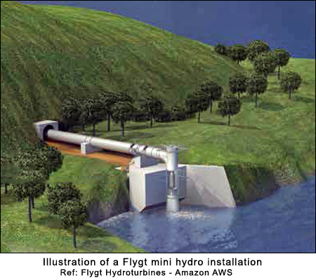
The above illustration is similar to the installation at Kamai 5.
At the Opuaki weir the river is diverted through tunnel 4 to the Ngatuhoa weir and water from both rivers is discharged through tunnel 5 into K5's penstock to the generator/turbine.
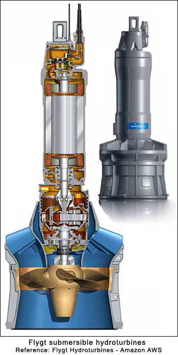
A straight conical draft tube recovers dynamic energy downstream of the turbine runner.
The Kaplan Turbine
This was a development of the Francis by an Austrian Professor Victor Kaplan in 1913. A basic axial flow turbine with fixed guide veins and runner blades suffers a rapid fall of efficiency at part loads. This is overcome in the Kaplan turbine which has adjustable blades in the runner.
With this arrangement a wide range of high efficiency may be achieved at varying power levels. Kaplans run from very low heads up to 400m and at ratings up to about 40MW .
With the machine axis vertical and turbine and generator totally submerged in a large bulb, this layout leads to a simple clean water flow over propeller-like blades - hence the name Kapeller.
Bulb Kapeller type turbines
The Kapeller Bulb turbine is a turbine regulated only by its adjustable runner blades (single regulation). It has fixed wicket gates. It is adaptable to pumping as well as generation but only suited to one way generation.
Kapeller Bulb turbine technology has largely been superseded by Bulb Kaplan turbines - these have adjustable blades and adjustable wicket gates (double regulation).
Reference: Water Power Article by Mike Hield http://rpec.co.uk/rpec_new/rpec.php
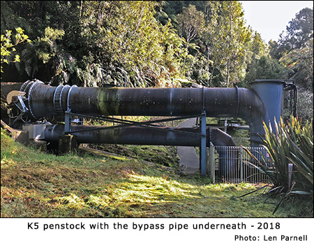
The pipe under the K5 penstock is a bypass with an electrically operated valve controlled by the Ngatahoa headpond level.
The valve will open when the level exceeds a certain value to pass excess water in a flood. The valve will also open when the main generator is undergoing maintenance .
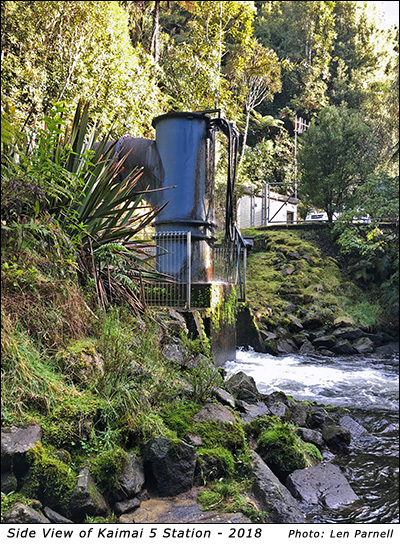
KAIMAI 5 POWER STATION (K5)
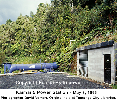
The building on the right houses a transformer and control panel.
The submersible hydroturbine is lowered into place down the vertical penstock section seen on the left. The hydroturbine is not bolted into the structure and can be easily raised for inspection and service.
The hydroturbine rests on and seals against a bottom seat and is held in place by its own weight and the water pressure while running.
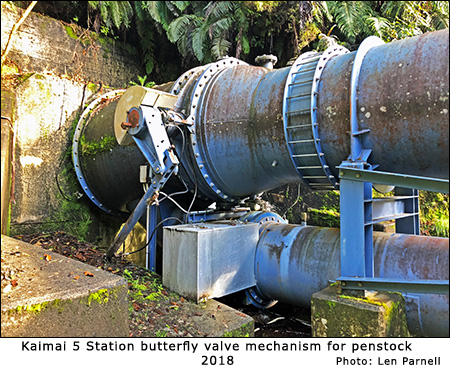
The ladder leads to an inspection manhole, and to the right of it is a butterfly valve, which acts as both a safety and maintenance device for the penstock.
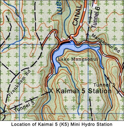
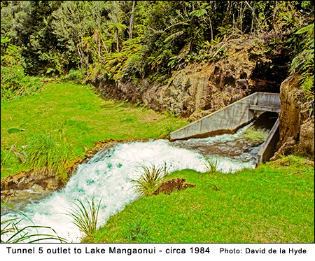
The Kaimai 5 Mini Hydro station is built at the outlet of Tunnel 5 Diversion tunnel into Lake Mangaonui. It was commissioned in 1994.
The station utilises a Flygt hydro turbine as illustrated on this page. The output is stated as 300kW and the head is approximately 5 meters.
Originally the station was expected to output 600kW but from practice it is said that 240 kW is a more realistic rating.
The station was commissioned in 1994.
A simplistic calculation for an output rating for K5:
Assume Lloyd Mandeno is correctly rated at 16MW and has a head of 151.5m.
K5 has a head of 5m and receives approximately half the water input of Lloyd Mandeno then:
Rating for K5 = (5/151.5)x16x 0.5 = 0.264MW (264kW)
Thus an output rating of 250kW or 300kW appears more realistic than 600kW.
Acknowledgements: I thank Harley Couper an Information Librarian at the Tauranga Librarys Heritage and Research Collection, and a Tauranga Engineer Roger Jamieson for their assistance.
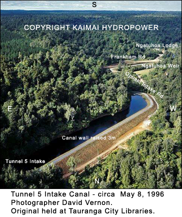
Addendum 4 July 2018: From a note sent from Roger Jamieson
"... In the photograph you have of the piece of canal you could not place in the scheme, it shows the canal with a raised wall. I think I am right in saying that this wall was not part of the original diversion from Ngatahoa and was added to raise the head for the K5 machine. If you add 3 metres to your calculation it gives closer to 400kW which may have been the original design figure. The roughness of the tunnel was blamed for the lack of output. It was supposed to be the first of the small plant in Kaimai, the next being at the control structure into the Lloyd Mandeno canal ..."
The photograph referred to is on the right.
Beside the transformer and contol panel building can be seen UHF aerials for communications and control.