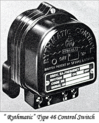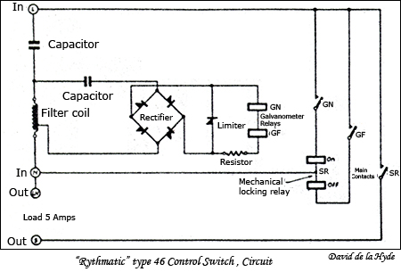
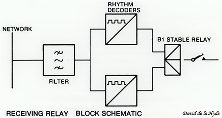
Circuit: A simple series type filter is used. The feed to the bridge rectifier and the galvanometer relays is tapped off the filter coil through a capacitor. The limiter serves to restrict the voltage of the rectified signal applied to the galvanometer relays.
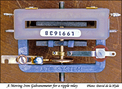
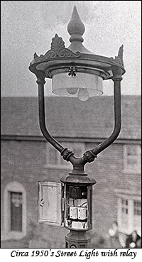
The signal coil is shown surrounding the top magnet. The movable counter balances on the bottom iron bar sets the resonant frequency.
The closing contacts can be seen above the spring coil.
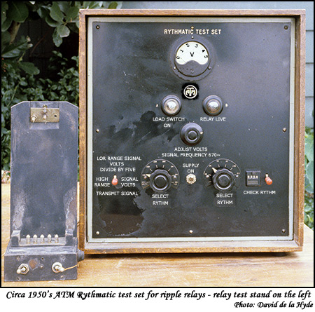
Note: Automatic Telephone and Electric (ATE). Previously known as ATM and later as Plessey Telecommunications Ltd. (PTL) and then as GEC-Plessey Telecommunications Ltd. (GPT).
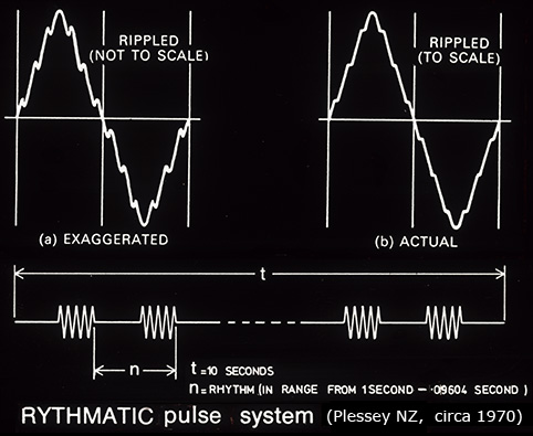
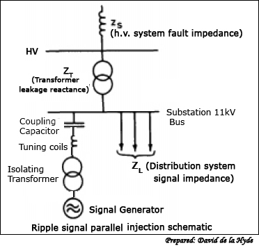
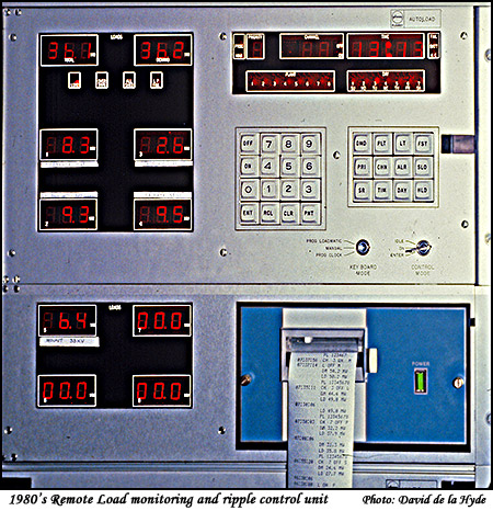
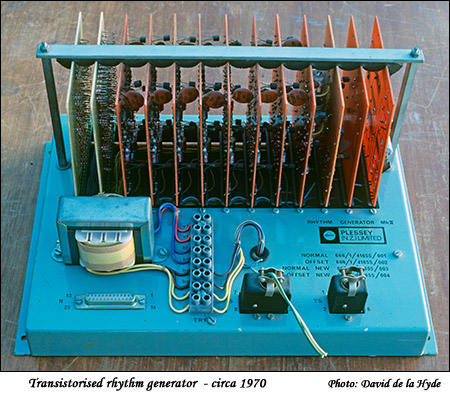
The generator frequencies used in NZ were from 175 Hz to 1050 Hz, and usually different in each network area to avoid interference.
The more common frequencies are in the lower frequency range such as 283 and 317Hz. Attenuation is greater at the higher frequencies and they were gradually phased out.
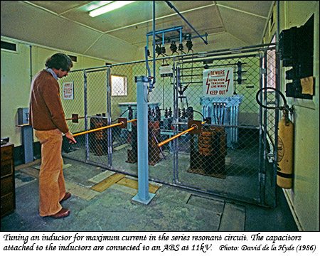
(The TEPB technician depicted is Chris Johnson who later worked for the DSIR and went to the Antarctic )
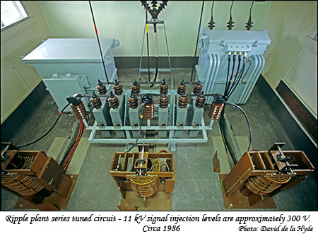
On the back left is the ripple frequency injection transformer connected to the generator output.
On the right is the local 50Hz supply transformer.
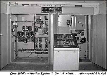
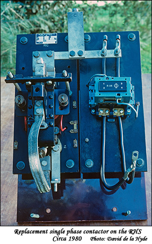
The photo on the left of the contactors on the output of the main signal generator illustrates the reason for a limited number of Rhythms used. The ealier single phase contactor depicted on the left of the picture had high inertia and the contacts prone to deterioration due to sparking. The lighter contactor illustrated on the right allowed the use of more signal rhythms.
The modern injection technology is the static frequency converter. Electronics is used to generate the injection signals which are again applied to the network via an isolation transformer and a tuned circuit. A much greater range of output frequencies and control coding is available by this method.
Circa 1980 galvanometer based ripple relays were replaced with transistorised receivers which were capable of receiving more complex signalling and varying frequencies.
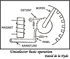
Elements of an Uniselector:
The basis of a uniselector is shown on the left. The attraction
of the armature causes a pawl, which engages with a
ratchet wheel, to push the switch wipers from one contact
to the next. The contact banks for the wipers normally
contain up to 8 levels each with 25 contacts.
The contacts
on each level are equally spaced and arranged in
semi-circular formation. The contacts are insulated from
each other and the levels are separated by spacers.
The
wipers are arranged in pairs so that both sides of the
contacts are "wiped" . The pairs of wipers are mounted
on, but insulated from a hollow spindle which is an
extension of the ratchet wheel. Connection is made to
the wipers by means of brushes of phosphor-bronze wire
or twin flat-strip springs riding in collector rings at
the base of the wipers.