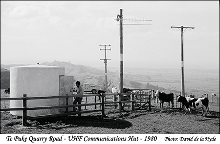
The picture above is not strictly relevant to the Wairoa Generation Scheme, but it does illustrate communications. I worked as a telecommunications engineer with the New Zealand Department of Civil Aviation before joining the Tauranga Electric Power Board in 1972.
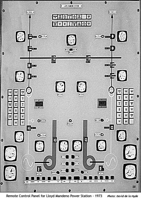
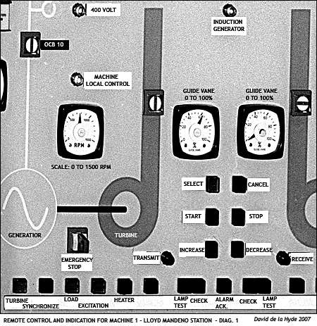
The layout of the panel is expained in sections in the left hand side of this web page and below.
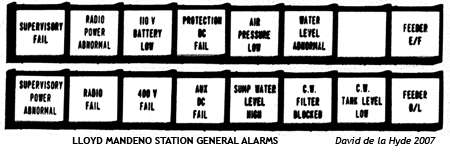
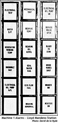
The above alarms are:
Supervisory Fail; Radio Power Abnormal; 110V Battery Low; Protection DC Fail; Air Pressure Low; Water Level Abnormal; Feeder Earth Fault; Supervisory Power Abnormal; Radio Fail; 400V Fail; Auxillary DC Fail; Sump Water Level High; Cooling Water Filter Blocked; Cooling Water Tank Level Low; Feeder Over Load.
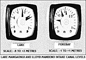
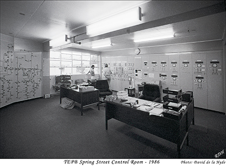
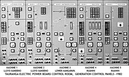
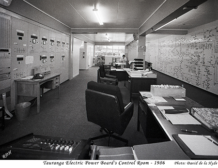
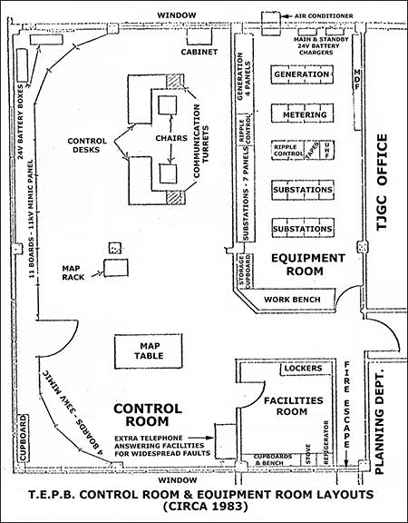
In the far corner, two people are in front of the TJGC Generation Control Panels, such as the Lloyd Mandeno Power Station pictured above. Then to the right is the Load Control Panel followed by the individual substation panels.
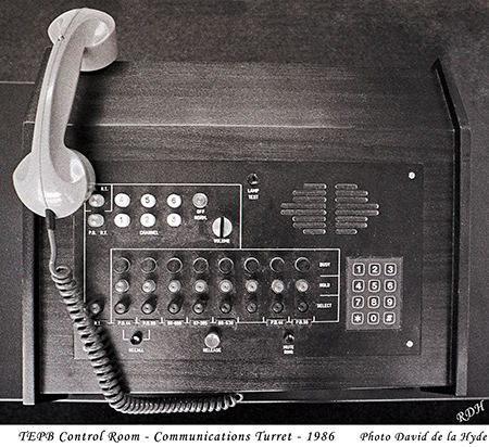
Each operator's desk had a "Communications Turret"
designed and built by TEPB (Tauranga Electric Power Board) to Post Office approval - illustrated on the left.
It had the following features:
(i) A calculator type key pad for dialing; the input
is stored and progressively, dialed out. TEPB
had one 100 line PAX at its Head Office
with trunk lines to other PAXs. The Board's
dialing system was reverse to the Post Office's
and this is automatically taken care of when a
line was selected.
(ii) All phone calls were answered with one handset and
both turrets were connected in parallel. When one
call was answered this was indicated on the other
turret by a flashing light going steady. A buzzer
is sounded when an incoming call was made.
(iii) Radio telephone calls through the Post Office base
station take priority over normal telephone calls
by means of a pressel switch on the hand piece.
(iv) All radio telephone calls were automatically
recorded and 5 seconds after the last speech was
detected a "speaking chip" recorded the time on to
the voice operated tape system.
(v) A standby trigger base transmitter could be selected
if the Post Office LDC line was out of action. All
radio telephone calls that are received were monitored
through a speaker. This assisted in emergency
situations when more than two people may be present
in the Control Room.
(vi) There was a table set up with telephone jacks behind
it, into which telephones could be plugged in. In
fault conditions extra personnel could be called in
to man the extensions and relieve the operators
from the burden of answering every call.