RUUD - GAS STORAGE WATER HEATER 1891
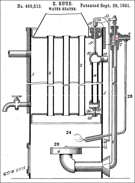
* In 1889, Edwin Ruud engineered a design for an automatic storage tank-type gas water heater that used a bottom gas heater and temperature controlled gas-valve.[8]. He later patented an improved design in 1891 which is shown above.
* The heater consists of the shell 1, having tubes or flues 2 passing there through. The burner 4 is arranged in a box or case below the heater and is connected by a pipe 6 to a valve-case 7, to which the gas-supply pipe 8 is also connected.
* The stem of the valve 9 (in red) is connected to one end of the lever 11, the opposite end of the lever being connected to a rod 17. This rod 17 passes through a stuffing-box 15 and is secured at its lower end to the expansion-tube 14, which is formed of a suitable material, preferably metal, having a higher coefficient of expansion than the metal of which the shell is formed.
* The expansion-tube is so constructed, as regards its upper end, as to prevent the entrance of the warm water in the heater in any considerable quantity. It is provided with an opening located in such proximity to the discharge end of the water-supply pipe 18, passing through the wall of the shell 1, that the cold water will flow into the tube 14 near its upper end and be discharged at its lower end.
* If water be withdrawn from the heater, cold water will flow in through the supply-pipe and passing down through the expansion tube will cool it. The consequent contraction of expansion tube will open the valve 9 and shift the plate-valve 20, thereby permitting the gas to escape through the burner and be ignited by the constant flame of the burner 24.
* As the water is drawn from the heater the cold water will flow into the expansion-tube, but its chilling effect will be partially counteracted by the warm water surrounding said tube, and hence the contraction of the tube will be comparatively small if a small quantity of water is withdrawn, but will gradually increase if a larger quantity is withdrawn.
* A small burner 24 is arranged over the main burner and is connected by a pipe 25 to the gas-supply pipe 8 at a point outside of the valve 9, so as to provide an igniting-flame for the main burner.
[4]
TOWN GAS - TAURANGA
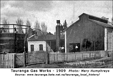
History of the Tauranga Gas Works.
Early in 1908, numerous proposals for lighting the borough were considered by the Tauranga Borough Council before it was finally decided to permit Messrs. Keene and Reid to erect a gas works.
When the council held a special meeting on Monday, January 6, 1908, the proposals were received. The Radium Gas Engineering Co., Wellington, offered to light the borough by private enterprise or for the municipality. The Shepard Acetylene Gas Engineering Co., Wellington, offered a scheme for lighting the town with acetylene.
At a meeting held a week later the council further discussed the two proposals for lighting the borough with gas, received from Messrs. Keene and Reid (Wellington), and Mr. Suggate (Auckland). The meeting adjourned, until Tuesday evening when it was decided that the Council adopt the recommendation moved by Mr. H. Southey the night before. The recommendation was: That the offer of Messrs. Keene and Reid for gas works etc., as amended be accepted by the council, subject to the contract being approved by the solicitor, as in terms of correspondence, provided and £ 50 be paid as deposit.
On Wednesday, September 23, Messrs. Keene and Reid advised the Borough Council that they had accepted the tender of Gibbons Bros., Dudley, England, for the supply of equipment for the gas works and mains complete for Tauranga.
The works were opened at 3 p.m., on Tuesday, August 17, 1909, when the late Rev. Canon Jordan (then mayor of Tauranga) turned on the permanent supply of gas to the town.
In spite of many vicissitudes the company flourished and before the works were bought by the Tauranga Gas Co. Ltd., in 1927, the company was run by the Keene family. The new company which started off with a capital of £4000 in £1 shares, owned the works until it went into liquidation on Tuesday, April 21, 1942.
Source: GAS WORKS TO BE SOLD PUBLIC AUCTION ON WEDNESDAY:
Bay of Plenty Times, volume LXXI, issue 13066, 8 February 1943
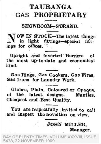
On Monday The 22nd Nov 1909 the B.O.P.T reported:
In the Tauranga Gas Proprietary's showroom on the Strand is now to be seen a large and varied selection of fittings and gas accessories. A practical illustration is given regarding the advantages of the distance lighter.
This is one of the latest things in gas conveniences and nay be placed near the head of a bed or other suitable place, and by simply touching a button the light, is turned on and off without even the application of a match at any time.
|
LLOYD MANDENO - AN IMPROVED ELECTRIC WATER HEATER
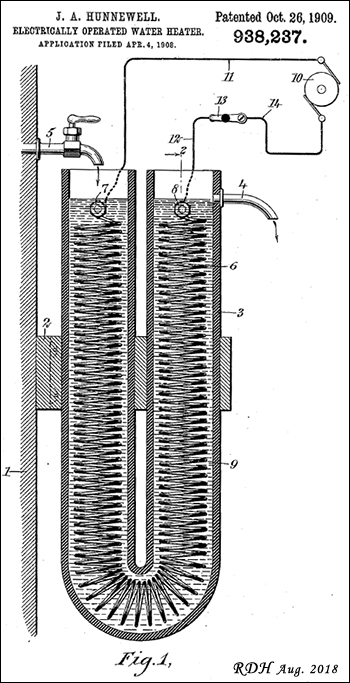
* Referring to the 1910 patent of J.E. Hunnewell above, Lloyd Mandeno did not develop the first storage electric water heater. However, it was one of the earliest designs in the world for an electric hot water cylinder. As it was five years later that Lloyd Mandeno installed his first electric storage heater in the house of Mr. R. S. Ready in Tauranga, it is likely that there were other similar developments.
* A particular feature of L.M's patent is the external water heating tube. Possibly suitable immersion heater elements were not generally available in 1915. The tube introduced the problem of de-scaling which LM designed for.
* In L.M's. 1923 paper " An analysis of the demand on the electric power supply of Tauranga, especially for cooking." he states - In the development of the water heater various troubles have been met with; one difficulty dealt with has been the vulnerability of the ordinary immersion element to damage by lightning and another met with in some districts is the scaling up of the element. These have eventually been dealt with by winding an element with a much higher arc over and with a greatly reduced intensity of heat on the heating surface. [9]
Thus it appears that he is patenting his original design of 1915
* In 1877 Samson Fox lodged a patent for his Corrugated Furnace. This was a tube (initially iron, later steel) heated and swaged (rolled) under pressure to form corrugations. This increased the surface area of the tube, allowing more energy to transfer from the fire to the boiler. The corrugations also provided additional strength to resist boiler pressure.
www.en.wikipedia.org/wiki/Samson_Fox
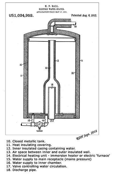
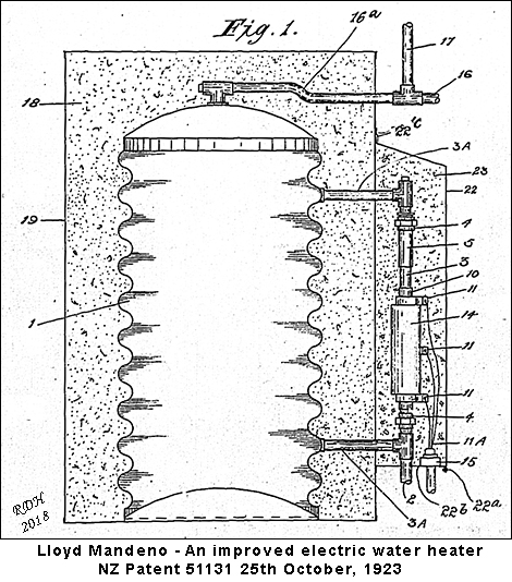
* Referring to Fig. 1 above cylinder 1 is heat insulated by the pumice 18 which is contained in the casing 19. The pipe 3 and heating element are heat insulated with pumice or ether suitable material contained within the hood 22. The front of this hood is detachable by means of a bolts 22a, 22b and 22c.
* Cold water enters the inlet pipe 2. The heated water is drawn from the top of the cylinder through the delivery pipe l6 which is trapped as shown at l6a and fitted with the vent pipe 17 which requires to be
extended above free water level.
* L.M. made the hot-water container of heavy-gauge corrugated galvanised iron and fitted two elements (350 W and 500 W). This sat in a larger container, around which he packed a 6-inch-thick (15 cm) layer of screened pumice for insulation, before placing it under the roof above the ceiling, with short drops of concealed pipe leading leading to the sink and the bathroom. [5]
* The corrugatedated sides of cylinder 1 and the domed base made the walls stronger compared to using flat metal.
* The fatal flaw in the cylinder design only became obvious after a couple of years the galvanised iron corroded
through. The solution, a copper cylinder, remains the basis for the low pressure electric hot-water cylinder still used in most New Zealand homes. [5]
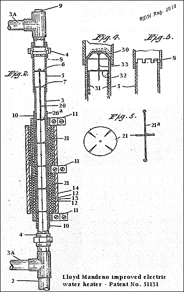
* Referring to Fig. 2 above the electric heating element is wound on the pipe 3 and consists of an insulating mica sheet 10 secured upon the pipe 3 by damping collars 11, the resistance wire 12 being connected between the collars 11 and each two adjacent turns of which are separated by asbestos thread 13.
The resistance wires may be wound in more than one layer by winding a further mica sheet over the first layer of the winding and then winding a further layer of resistance thereon as shown.
A serving of sheet asbestos 14, or other suitable heat insulator, is wrapped over the heating element to conserve heat. The connecting wires 11a from the collars 11 are led into the conduit box 15 (Fig. 1) for connection to the supply circuit.
* A light piston 6 acting as a valve and working in a slightly enlarged portion of the pipe 5 near the top thereof, normally rests on a seat 7 formed by the top of pipe 3. Piston 6 is free to lift against gravity up through the enlarged portion of pipe 5 until it reaches a number of ports 8 (Fig.3) in order to allow the escape of steam from below the piston 6 when it is in the upper portion of its stroke.
Steam escapes through ports 8 and the heated water passes until equilibrium of pressure is obtained in the pipe when the piston will return by gravity to its seat thereby again closing the pipe.
* The piston 6 is rigidly connected to a rod 20 which slides in pipe 3 below it. . Suspended from the rod 20 are a number of discs 21 serrated as shown in Figure 5 whereby water may pass them. These discs are linked together by loose fitting joints, preferably as shown in Figure 5, where the disc 21 is shown fixed to the rod 21a which is provided with hooked ends whereby such rods maybe connected together.
The piston 6 with the guide 20a, owing to their regular rising and falling movement, move the serrated discs 21, and so by friction against the inside of the pipe 3 prevent the adhesion of scale or other deposit on the heating surface.
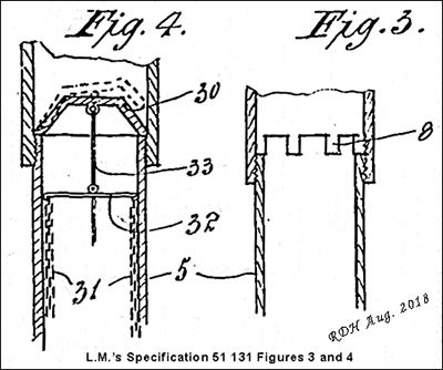
* Figure 4, shows a modified form of control device which consists of a loose dish shaped valve
30 adapted to be normally seated upon the top of the pipe 5. Loose chains 31 are suspended from a bar 32
attached to a rod 33 suspended to the underside of the valve at its centre as shown, so as to be above the centre of buoyancy of the valve.
The chains prevent the adhesion of scale in the same way as the discs 21 (Fig. 2).
When steam generates and fills the dome of the valve it will tilt the valve, as indicated by the
dotted lines, permitting the steam to pass out and water to circulate.
[6]
|
TAURANGA BOROUGH COUNCIL'S ELECTRICAL SHOWROOMS, DEVONPORT ROAD -16 JUNE 1915
There is now in the Borough Council's Electrical Showrooms. Devonport Road, a very handsome and effective display of electrical goods.
On entering, the first, that greets the eye is a magnificent showing of adjustable fittings for home or shop lighting, the main part of which is mostly made of oxidized copper, carrying from one to four lamps, the globes of which are in every shade imaginable and when lit up make a very brilliant show.
On the switch board itself is recording voltmeter which draws curve showing the electrical pressure at any time of the day. This it keeps most accurately.
The Coffee Percolator is invaluable to any coffee drinker who appreciates good coffee. The water is put in cold and thirty seconds after the current is switched on boiling water is sprayed over the coffee, which, on pouring out, is absolutely free of grounds or sediment.
Electric toasters are also represented. These can be had in nickel plate or porcelain. They can he placed on the breakfast table and your toast is made during the progress of the meal.
Hot plates or electric rings for boiling kettles, and stoves for boiling, toasting, and grilling, are included in the display.
Electric irons in all sizes are in full working order. The beauty of these irons is that they can be used without the heat being felt by the user, as is the case in other irons. There is also an apparatus, which, when attached to an iron, makes a stand on which water can be boiled or other articles of food cooked.
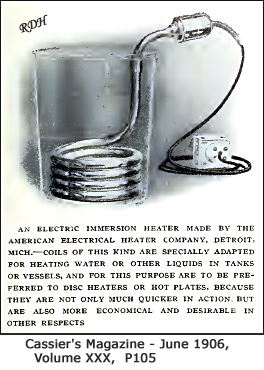
The immersion heater, which in appearance is something similar to a bicycle pump, is a very handy, clean and useful article. When immersed in water, milk, or any other liquid it brings it to a boil in a very few minutes Electric kettles, self-contained, are shown in all makes; you simply press the button and in a short space of time your water is at boiling point.
Turning to the lamps, stocks are carried from 10 to 3000 candle power. The lighting element of the high efficiency lamp consists of a very fine tungsten, which, although far harder than steel itself, is worked into a spiral, but so fine that the eye can hardly detect that it is a spiral.
This filament itself is supported on a wire spider in the centre of a glass bulb filled with nitrogen gas, and these lamps are specially used for outside lighting, public buildings and business premises. The light is so intense that special fittings are used for softening it. The cost of burning a 400 c.p. 1/2 watt lamp in Tauranga is not more than 1.75d an hour.
Radiators for heating offices or rooms of the very latest designs are also shown.
Reflectors are stocked in all shapes, focusing, intensive and extensive. These are made in the form of prisms, which produce a highly ornamental appearance. The idea of the shapes is that the light can be distributed or concentrated as desired. Besides these there are reflectors for shop use, by means of which an efficient light, without any glare, can he secured.
Pressed steel stoves, double walled, with heat insulation between, which reach cooking temperature three minutes after the current has been switched on, and having glass fronts through which can be seen the progress of the cooking without opening the door, with a special switch fastened to the stove for regulating the heat, are not the least interesting articles in this very comprehensive display of electrical fittings.
Switches of a very highly ornamental nature are also to be procured in the very latest French designs. Last, but not least, we come to the Vacuum Cleaner or Sweeper,- you simply switch on the current, and the carpets, mats, etc., can be thoroughly cleaned instantly without being lifted from the floor.
The cleaner has a special bag attached to it into which all the dust and dirt is sucked by means of a small motor attachment, and the bag itself can be detached for emptying purposes by simply turning a screw.
The display generally is evidence of the intention of the Council to do its utmost to push the sale of its electric current, and the Boroughs Electrical Engineer, Mr.. Lloyd Mandeno, is to be complimented on the very thorough and pleasing display that he has been able to get together in the short time he has been here.
Every evening from 5 to 6 and from 7 to 8.30, a display will be given at the Show rooms, and on Saturdays from 7 to 9.30. To meet the convenience of inquirers Mr. Mandeno will be at the Show Rooms daily from 9.30 to 10 30 am, and from 2.0 to 3.0 pm, to answer questions and explain the various appliances.
BAY OF PLENTY TIMES, VOLUME XLIII, ISSUE 6111, 16 JUNE 1915
AMERICAN - 'ALL ELECTRIC HOME' - 1905
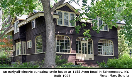
The house at 1155 Avon Road in Schenectady, NY is known locally as the house without a kitchen chimney.
The head of the Electric Heating Department at GE (General Electric), Harry W. Hillman, used his position to his advantage when building his Avon Road property in 1905, his second house in the Plot. Designed as a demonstration house, this house had two circuitsone for a lightbulb, and a second one which could be used for appliances. Other electrified houses only had one circuit per room which made Hillmans house extra-special, earning it recognition as:
ONE OF THE FIRST ALL-ELECTRIFIED HOUSES IN THE COUNTRY, - (1905, America)
With reference to the all electric home shown above, Harry.W. Hillman read a paper at the Association of Edison Electric Illuminating Companies. The association decided that a committee of engineers should verify Hillmans claims. Their decision and recommendation were that electric heating and appliances should be vigorously pursued by the member companies. This led to the development of refrigerators, stoves, and products that today most people would have difficulty living without.
Note:
Mr H.W.Hillman used an immersion heater to provide for hot baths. Because it snows in Schenectady N.Y. in winter, he had a hot air furnace installed, to heat up the kitchen and laundry in particular. There was also a fireplace in the Living Room.
https://dailygazette.com/article/2017/06/25/the-hidden-history-of-the-ge-realty-plot
https://blog.timesunion.com/rittner/first-all-electric-house/265/
Reference: Electrified Houses - PDF Files:
Hillman, H.W., "An Electric Day," Good Housekeeping, June 1906
Includes wiring diagram for H.W. Hillman's 1905 house.
Hillman, H.W., "Electricity in the House", Cassier's Magazine, November 1906
Knowlton H. S., "Extending the uses of Electricity its applications to Domestic Service", Cassier's Magazine, June 1906
Lees, F., "An Electric Villa", Strand Magazine , September 1907
Kennelley, A.E., "Electricity in the Household", Scribner's Magazine, 1890
|
LLOYD MANDENO AND THE PROMOTION OF ELECTRICITY.
Lloyd Mandeno graduated with an Electrical Engineering degree from Canterbury College in 1909, and then spent two years - (circa 1909 - 1911) as a personal assistant to the manager of Turnbull and Jones - Mr. F.A. Brown (also an electrical engineer), in Auckland.
It is likely that Mr Brown's experience was primarily in DC motors, DC generators and Battery systems. A factor in employing Mr Mandeno may have been his freshly completed university training which would have included AC Motors, Generators and Transformers.
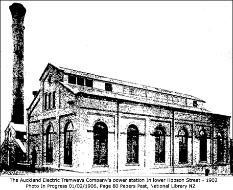
The public supply of electricity in Auckland (DC based) appears to have begun with the inauguration of the Auckland Electric Tramways Company's power station in Lower Hobson Street on Monday 17 November 1902. Prior to this entities that required electricity had to provide their own generators driven by gas engines, steam engines or via hydro power.
The original plant consisted of three horizontal compound engines, each direct coupled to a 300 k.W. direct current generator, steam being supplied by four Babcock and Wilcox water tube boilers. 550V DC was supplied by underground cables to the Tramway system.
Other consumers (including the Council) in the central city area were supplied by a three wire direct current with 440V between the outer wires. Later a 460V DC three wire system was introduced from the Councils Destructor Station.
The system also incorporated four boosters, each consisting of a shunt-wound motor direct coupled to a series-wound generator. It was calculated that there would be required on the negative side one booster to give 20 volts at 400 amperes, and two giving approximately 110 volts at 330 amperes, and on the positive side one booster to give 105 volts at 250 amperes.
With a DC system, to compensate for voltage drops along along feeders, either boosters as described and/or large battery banks were used to raise the voltage at the generation station. To extend the range of supply, a lower DC Voltage could run a DC motor to drive a generator at the required voltage level to supply outer areas.
With an exception of very long distance power transmission, DC distribution systems are limited in their range, and more expensive compared to using an AC system with higher transmission voltages, and transformers to lower the voltage to the level required by the consumer. For a given load, a higher voltage reduces the current required, and thus lowers the losses due to line currents.
In 1906 an Australian Engineer Mr. W.T.G. Goodman gave a proposal to the Auckland City Council of using their rubbish Destruction Plant in Hobson street to generate electricity. This was a DC system designed to be compatible with the existing Tramways reticulation. The Council accepted and Turnbull & Jones were awarded the contract of installing a generating plant for £11,808.
The opening ceremony for the City Councils Electric Power Plant at the Destructor site in Freemans Bay took place on the 10 February 1908.
The engineroom contained two high speed enclosed engines of 300-horse power each, coupled direct to the two generators of 225 kilowatts each. A "booster plant, from which the batteries are charged, was installed in that room, whilst the switch board, from which the whole supply was controlled, was also in the same compartment. The battery-room, which was on the east of the engineroom, contained 260 storage calls of large capacity, which was considered to be ample for all requirements for a considerable time to come.
Thus consumers at that time were supplied with DC. The Battery Plant assists with voltage regulation and could give supply to a feeder that has a relatively light load.
In 1910 the equipment of the engine-room at the Tramways central power plant was added to by the erection of a 600-kilowatt steam alternator, with a voltage of 5500 (AC), as well as a 500-kilowatt motor generator (DC). The former to supply power to the Epsom sub-station, whilst the motor generator acted as a reserve for use during hours of light load.
The Tramways sub-station which had been erected at Epsom adjoining the car depot, was installed with two 500-kilowatt (AC) motor and (DC) generators sets, one set being used at a time, the second set serving as a spare, and the usual standard high-tension and low tension switch-boards.
The current after being generated at the main station at a voltage of 5500, was conveyed to the Epsom sub-station by means of two extra high tension three core paper-insulated, lead covered and steel armoured cables. These cables were laid in a conduit system as far as Newmarket, and from there to the sub-station they were laid "solid" in Doulton earthenware conduits, filled with bitumen.
While employed at Turnbull & Jones, Lloyd Mandeno assisted with the installation of the first alternating current plant in Auckland (described above); with the preparation of tenders for the Kings Wharf Generating Station; mechanical layouts of lift installations and feasibility studies of small hydro-stations for individual farmers.
After L.M. left the employment of Turnbull and Jones he assisted with the installation of electrical equipment at the Waihi Mining Company's Hora Hora hydroelectric power station. Then he spent a year or two as a borough electrical and civil engineer in the borough of Frankton, before his appointment as borough electrical engineer at Tauranga early in 1915.
The Omanawa Station was completed on the 28th August, 1915 and on 2nd October, 1915, the Tauranga Borough was lit up for the first time with electrical street lights replacing the existing gas lamps. The output from Omanawa was carried to the Borough on a three phase 11kV line.
Thus the first task for Lloyd Mandeno, in Tauranga, was to promote the use of Electricity. His experience with Turnbull & Jones in Auckland would have helped as that firm sold and displayed electrical appliances. He organised a showroom in Devonport Road which opened mid June 2015. Electricity was generated with a dynamo driven by an oil engine.
One of the visitors was a Mr. R.S. Ready who he persuaded to build a home with no chimney. This enabled a significant cost saving. For the provision of hot water he designed an electric hot water storage cylinder which is described above.
After a century with no evidence to the contrary, Mr. Ready's house appears to have been:-
THE FIRST HOUSE IN NEW ZEALAND DEPENDENT ON A PUBLIC ELECTRIC POWER SUPPLY FOR ALL ITS ENERGY REQUIREMENTS & incorporating one of the world's first designs of a cylindrical electric hot water storage system - (1915, New Zealand)
Reference: General PDF Files:
Progress - Electric tramways NZ no 4 Auckland Feb 1 1906
Auckland - Opening of Destructor Plant 8 Feb. 1908
Auckland - Electric Power Plan Approved 21 Jan. 1910
Epsom - New Tramways Substation 21 July 1910
Auckland - Kings Wharf Power Station Proposal 9 Nov. 1910
Auckland - Tramways Power Station Description 11 Feb 1911
Tauranga - Omanawa Supply Switched on 4 Oct 1915
Tauranga - Gas Works Description 18 AUG 1909
Tauranga - History Gas Works 8 Feb 1943
|